How the animations are made
A lot of folks send me email asking how these animations were made. The process I use is a laborious one that I can’t really recommend if you want to do this regularly.
What follows is only an outline. Please understand that this not a complete tutorial.
Here are the steps:
- Create a drawing in a CAD (Computer Aided Design) program.
- Copy it several times and move the parts in each copy a little to suggest the motion.
- Export each copy to a separate image file.
- Combine the images to create an animated GIF image.
Most of my time is spent in the CAD program. A CAD program is a computerized drafting board. DesignCAD is the one I use, but I think any reasonably capable CAD program would do, as long as it has the ability to export images. Most of the work has to do with using the CAD program itself, so I’ll defer to the user’s manual for that part.
Note:
You should be very handy with your CAD program before attempting to create an animation this way. Unfortunately CAD programs all seem to have a fairly steep learning curve. If you’re brand new to this, plan on spending a few weeks just learning how to use the CAD program. If you learn how to write macros for your CAD program, you’ll be ahead of the game; but it’s not absolutely necessary.

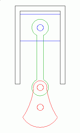
Once the basic drawing is complete, combine, or group, all of the lines and curves that form each moving part. Then combine all the remaining, non-moving lines into a background group. This makes it easier to manipulate individual parts without disturbing the other items in the drawing. In the above illustration, the groups are also distinguished by their color: red, green, blue, and black.
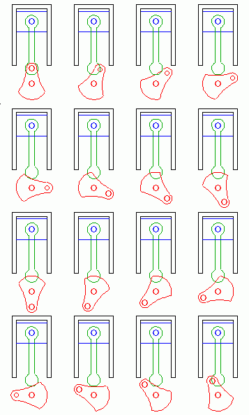
Then, duplicate the entire drawing several times to create the individual frames. The number of frames varies depending on the detail you want. This example uses 16 frames, which seems to be about the minimum. I’ve written a macro for my CAD program to make this task easier.
Now comes the most laborious task. Move each moving part just a smidge for each frame. This takes a little practice and planning to make sure that the completed animation works smoothly.
I usually start with the crankshaft, and then adjust the rest of the parts to match. If you are using 16 frames, then your crank should rotate 22.5 degrees for each frame (360/16 = 22.5). I have another macro to duplicate and rotate parts, because this is such a common operation. The illustration below shows the drawing duplicated with the crankshaft already rotated.

If there are spoked wheels or gears in your drawing, be extra careful with the number of frames you choose, or the parts might appear to be rotating too fast, two slow, or backwards—like wagon wheels in an old western movie. My solution is to make sure the gears rotate exactly 1/2 tooth (or some odd multiple) per frame. This might mean you have to rearrange the number of frames or gear teeth.
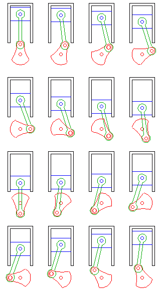
Parts like connecting rods and pistons must be manipulated by hand to correspond to the new position of the crank. I usually have to draw a few lines and arcs to figure out the new position of each part. Here’s a typical sequence of operations:

When I’m done with that step, the drawing looks like this:

Next, I add the gas bubbles and other effects. This makes the illustration much easier to understand, but it’s so tedious I’ve skipped it on a number my animations, including this one—sorry, that’s just too much work!
Then, I export each frame to a separate image file. It’s important to make sure that the images are all the same size and orientation so the frames align correctly. I wrote another macro to accomplish this task.
Finally, I combine the separate frames into an animated GIF file. I use PolyView (a terrific shareware image utility) for this step. An animated GIF is an image file that contains several frames intended to be played back in sequence. It’s probably the simplest type of animation available on the web. Most browsers have built-in support for displaying them.
Here’s the result:
I’m sure there are better tools out there for doing this sort of thing. If you decide to try doing it my way, let me know. I’ll try to answer any questions you might have, but as you can see, this is a complicated process so I can’t make any promises!
Good luck!
The Control Panel
The instructions above describe the technique for creating an animated GIF image. These can be imbedded in a web page as easily as a static image.
I now use a different animation method in order to support the control panel feature. Everything discussed above still applies. The difference is that the images are saved in a static format and are animated by a small Javascript program.
I hope to thoroughly document this new technique sometime soon. If you’d like to be notified when I do, keep in touch.

 Follow
 Befriend
 Subscribe